
|
Eager Space | Videos by Alpha | Videos by Date | All Video Text | Support | Community | About |
|---|

Why did the shuttle look so weird? https://www.youtube.com/watch?v=qUxxKSBu-Ss
Roger's commission report on challenger:
https://sma.nasa.gov/SignificantIncidents/assets/rogers_commission_report.pdf
Roger's commission chapter 6:
https://www.nasa.gov/history/rogersrep/v1ch6.htm
Truth, Lies, and O Rings:
https://www.amazon.com/Truth-Lies-Rings-Challenger-Disaster/dp/0813041937
We've all seen the video...
https://www.youtube.com/watch?v=rUqPMMgfJ4Q
(video plays until "go for throttle up" call, and then freezes.
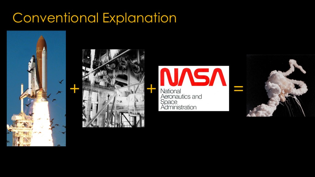
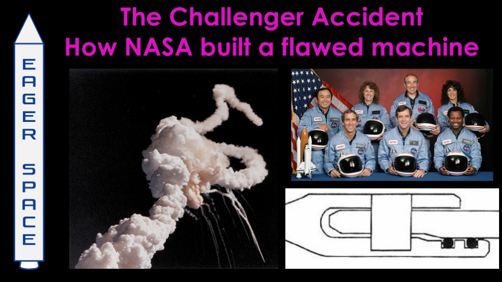
The conventional explanation is that if you take a space shuttle, add in some very cold weather in Florida, and add in a flawed NASA decision making process, you end up with an explosion that kills an entire crew and destroys a multi-billion-dollar vehicle.
I think that's a pretty good explanation, and the details around how NASA decided to launch are interesting to people who study organizations, and that *is* one of my hobbies.
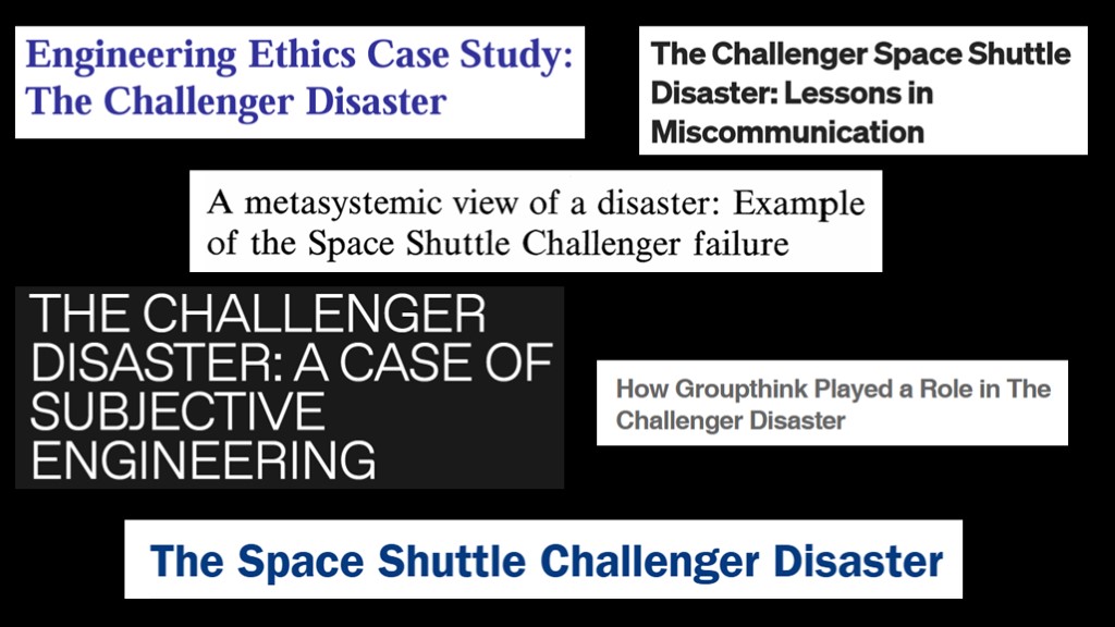
But there have been hundreds of papers written on what went wrong inside NASA that led them to launch that day, and quite a few books as well, and I therefore didn't think there was much that I could add.
But there is a related question...
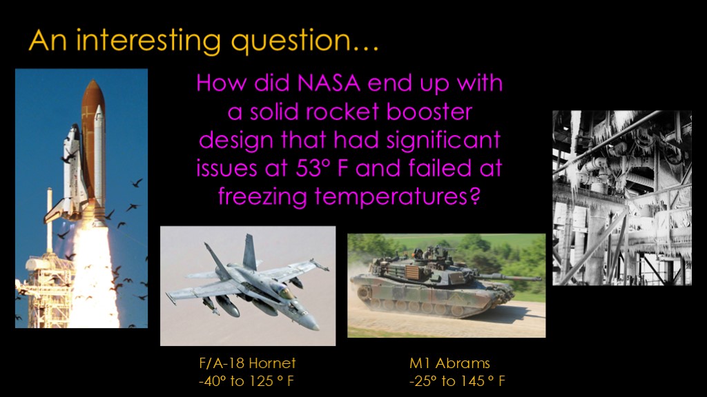
How did NASA end up with a solid rocket booster design that had significant issues at 53 degrees and failed at freezing temperatures?
The F/A 18 hornet fighter operates from -40 to 125 degrees Fahrenheit, and the M1 Abrams tank operates from -25 to 145 degrees. Those are more sophisticated than the solid rocket boosters, and they do fine in cold temperatures.
And - not to put too fine a point on it - the post-challenger solid rocket booster design was essentially perfect for the rest of the shuttle program.
Answering this question is the purpose of this video.
To start, we need to understand how NASA ended up with solid rocket boosters in the first place.
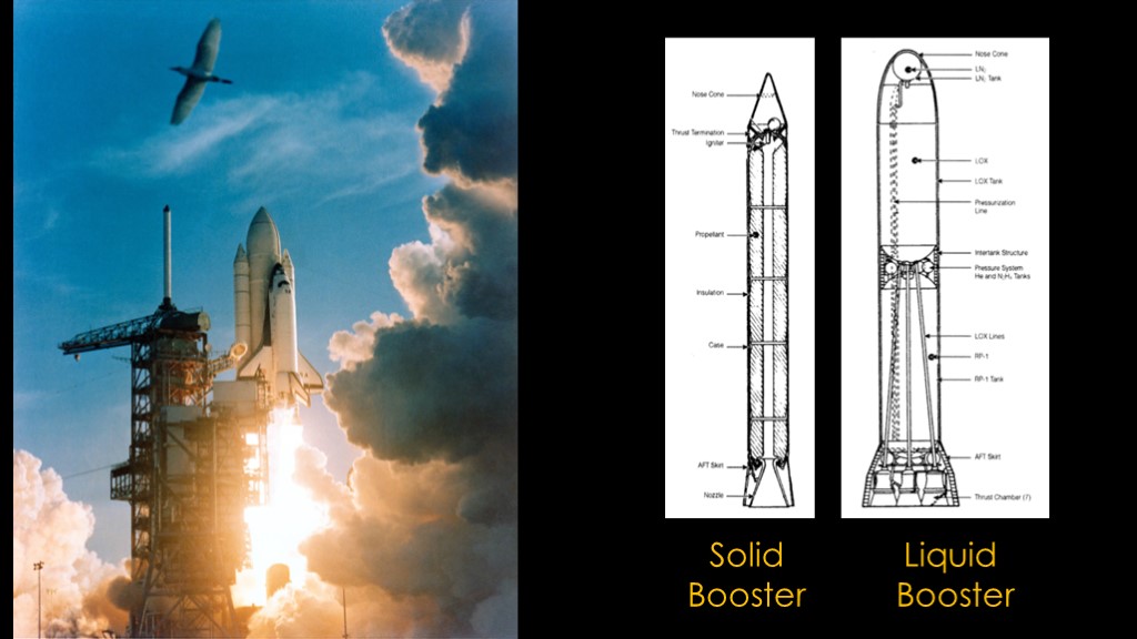
As NASA had never launched astronauts with solid rocket boosters, it seems to be a weird choice. Liquids are generally considered to be better in most ways compared to solids, but the place where solids win is development time and cost - they are quicker and cheaper to develop - and since the shuttle budget was very limited, NASA had to choose between a shuttle with solid rocket boosters or no shuttle at all.
That decision was easy.
There was one issue with choosing a solid rocket booster, and that was weight.
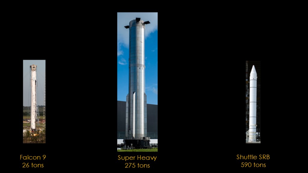
An empty Falcon 9 booster is about 26 tons and can be transported on the road - barely.
The super heavy booster that lifts starship off the ground is the biggest booster and weighs around 275 tons. It needs a special crawler to be transported and doesn't go very far.
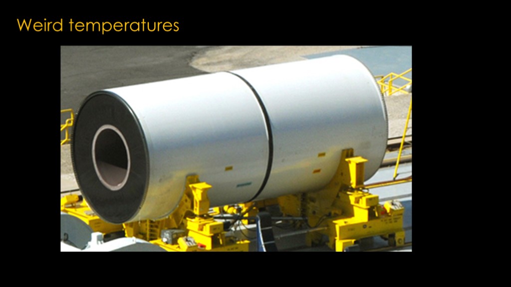
A shuttle solid rocket booster that is a few meters shorter than a Falcon 9 booster weights 590 tons.
The difference is that liquid fueled rockets have no propellant in them when transported, and solid rocket boosters have all the propellant inside when they leave the factory.
If you could build them near a port somewhere, you could maybe use a ship to get them to Kennedy space center - the large Saturn V first stage booster was transported that way - but shuttle was going to launch from Vandenberg air force base, which has no easy port access.
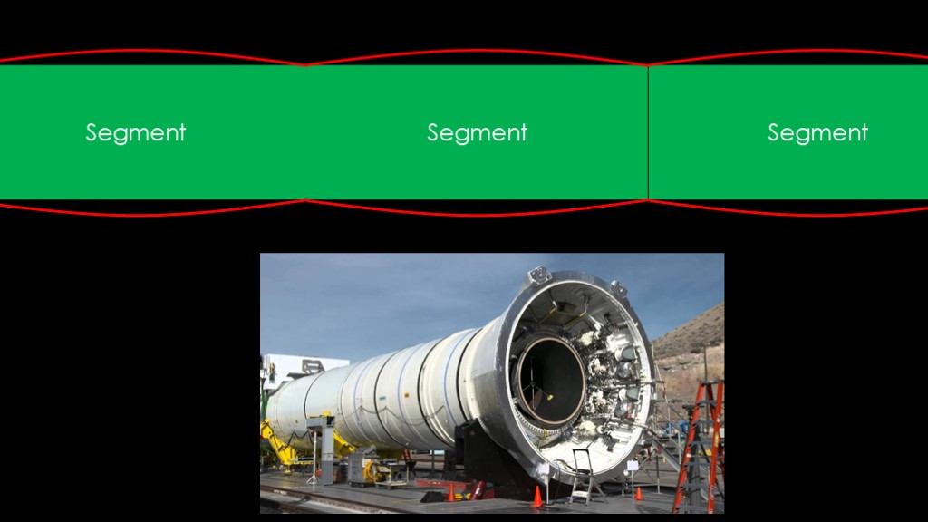
What you need is a solid rocket booster that can be transported by rail in sections and then assembled at the launch site.
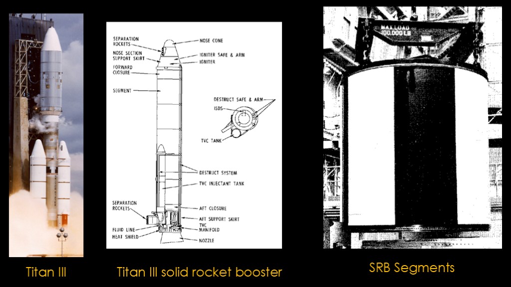
The solution for this had already been developed; the air force's Titan III used two large solid rocket boosters that are made in pieces, known as segments.
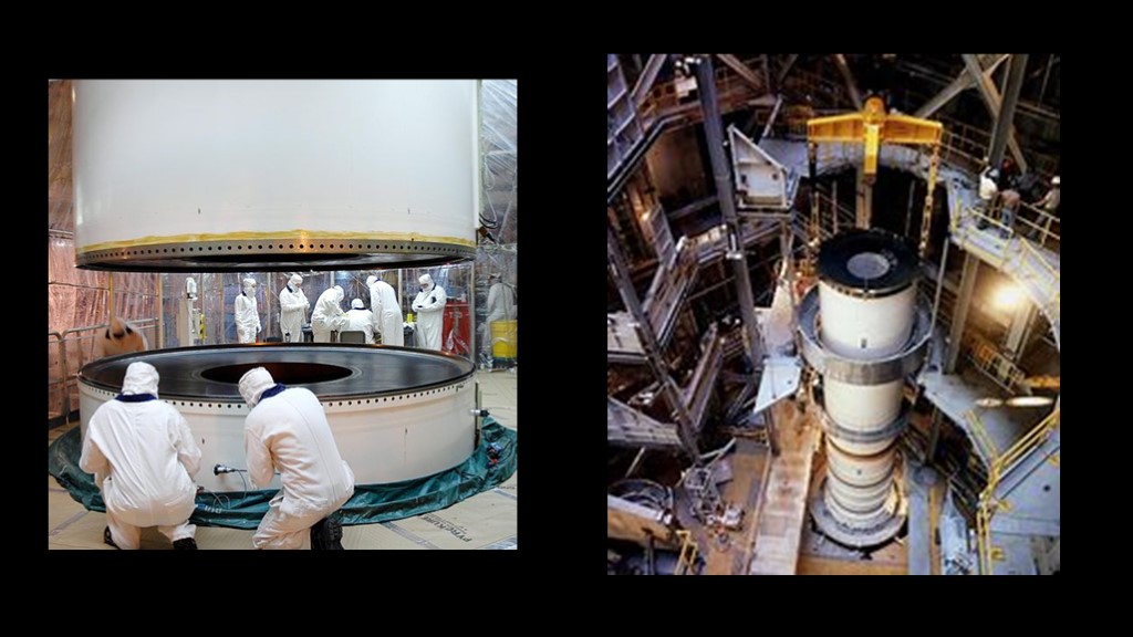
The segments are shipped from the factory and assembled - or stacked - to make the final booster. The joints between the segments are called "field joints" because the segments are joined in the field, not the factory. It is one of these field joints that failed during the flight of Challenger.
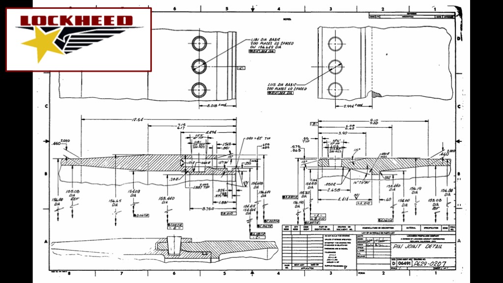
One of the finalists for the shuttle solid rocket booster contract was Lockheed. Lockheed based their design on the Titan III booster but wanted to do a better design for shuttle. Lockheed nicely included this great engineering drawing in their proposal and that makes it very easy to understand their joint design...
If you are fluent at reading engineering drawings. Since some of you likely aren't, I drew up the design in CAD and created a little animation that describes what the joint looks like and how it is assembled.

The whole point of the joint design is to keep the flamey stuff from leaking out of the booster. The joint has two parts.
A clevis is machined into one end of a segment, and a matching tang machined into the other end of the segment that it will connect to.
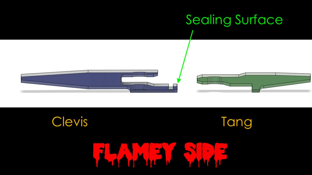
The clevis has a flat section known as the sealing surface.
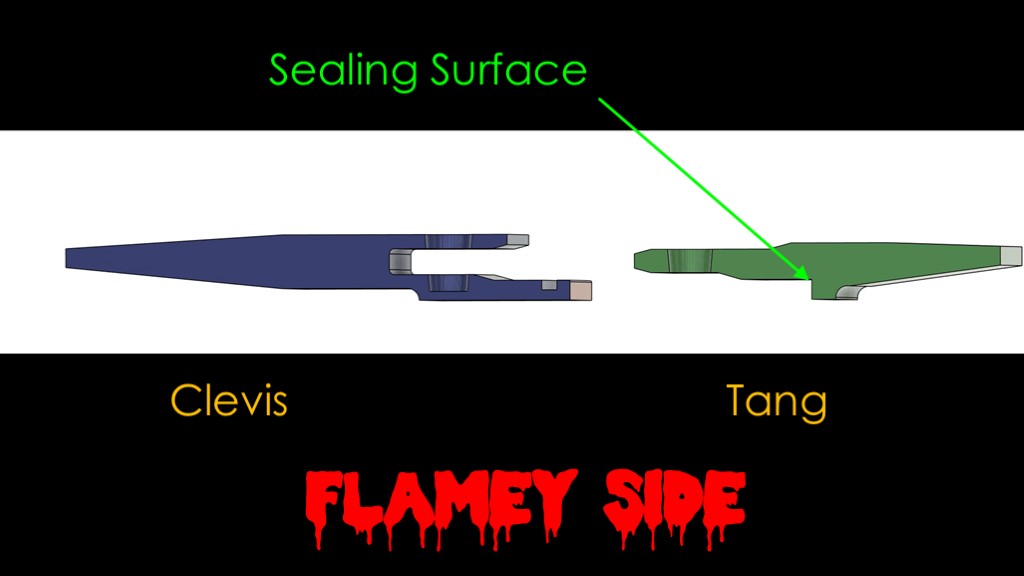
The tang has a matching sealing surface.
The clevis is inserted into the tang, but notice that there is still space between the two sealing surfaces, which is bad.
To get that fit as tight as possible, the design uses a tapered pin that is inserted from the outside. As the tapered pin is pressed into the joint, it pulls the tang into the clevis and jams the two mating surfaces tightly together, giving a good seal.
If there is any combustion gas that sneaks by the sealing surfaces, there is an o-ring that prevents the gas from escaping the joint.
The clevis and tang design is machined all the way around each segment, and there are 200 tapered pins that hold the two segments together.
The tapered pins exert a lot of pressure, and I call this a "as close as possible to a single chunk of steel" design. It's honestly a great design.
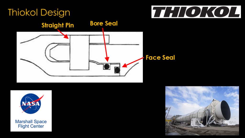
NASA, however, did not choose the Lockheed design. They chose a competing design from Thiokol chemical company, and NASA administrator James C. Fletcher assured everyone that the decision to choose Thiokol had nothing to do with the fact that Thiokol was located in his home state of Utah or that two of the engineers on the evaluation board had previously worked at Thiokol.
The Thiokol design looks very similar to the Lockheed design. The first thing you probably notice is that there is an extra o-ring in the design - in addition to the bore seal o-ring used in the Lockheed design, there is a face seal o-ring. If we look a little closer, we can see why - this design uses straight pins rather than tapered ones, and that means that the two faces will not be tightly held together, so the idea of the face seal o ring is to seal the faces together.
Some of you may have noticed that this is not the joint design that flew on Challenger.
And that's because NASA's Marshall Space Flight Center in Alabama - the NASA center that was responsible for the solid rocket boosters on shuttle - did not like the design. They argued that tapered pins were required to keep the face seal tight, as the Lockheed design used.
Thiokol was also worried about assembling the solid rocket boosters horizontally for the test firings they would do. Gravity will distort the segments slightly when they are horizontal, and the clevis end has more steel so it distorts less. That means the segments don't fit together very well.
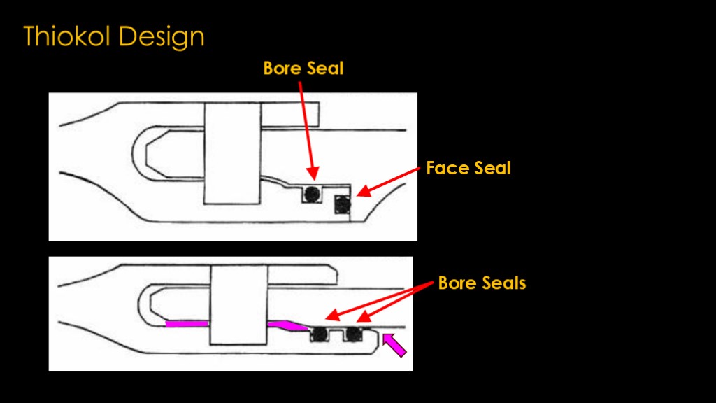
Thiokol went back to the drawing board and came up with a new design based on the Titan III. The Titan III had a lot of flight heritage and a great reliability record, and they therefore duplicated the Titan III design with an additional o ring.
In a face seal design with tapered pins, the two faces are about half an inch wide and are strongly clamped together by the pins. Combustion gas can only get into the joint by leaking between those very tight surfaces, and that limits the flow and therefore the amount of heat that can get into the joint to attack the o ring.
The new design depends on the end of the clevis staying close enough to the tang to keep the o-rings sealed, but there is no clamping pressure to keep those two points in contact - it depends purely on the strength of the tang and the joint not moving.
Worse, in a move to make horizontal assembly easier, Thiokol increased the tolerances - they added space - between the clevis and tang.
Basing a new design on a proven design is generally a good thing. But objectively, this is a terrible design.
And now is a good time to talk about o rings...
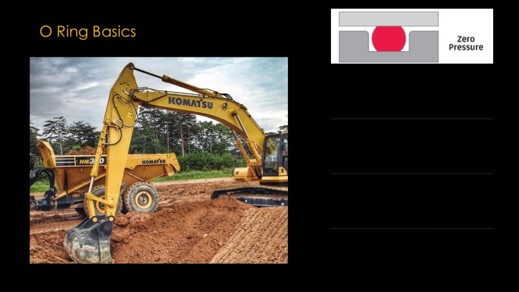
O rings are used to seal two surfaces. In this cross-section view, the bottom surface that has a square groove milled into it, and an O ring is put into that groove. It's made of an elastomeric material, which is a fancy way of saying that it can compress and deform and return to its original shape. As a generic term, "rubber" is pretty close.
The second surface is then put on top of the first surface. The O ring is sized so that the o ring is compressed by a specific amount - typically 15 to 25% of its diameter.
When we apply pressure from one side of the o ring, the pressure of the o ring on the two surfaces keeps the fluid from leaking to the other side, and it pushes the o ring to the other side of the groove. The pressure of the fluid changes the shape from a compressed circle to more of a "D" shape, and the pressure of the fluid is converted to pressure of the o ring on the surfaces, effectively blocking the fluid. As pressures go up, part of the o ring starts to get pushed out the other side groove space, and if the pressure gets too high, it will extrude enough to break the o ring.
O rings are in everything - any device that has pressurized fluids or gases typically uses them. The hydraulic cylinders in construction equipment have complicated seals that use o rings to keep the high pressure hydraulic oil properly contained. They are highly reliable when properly designed.
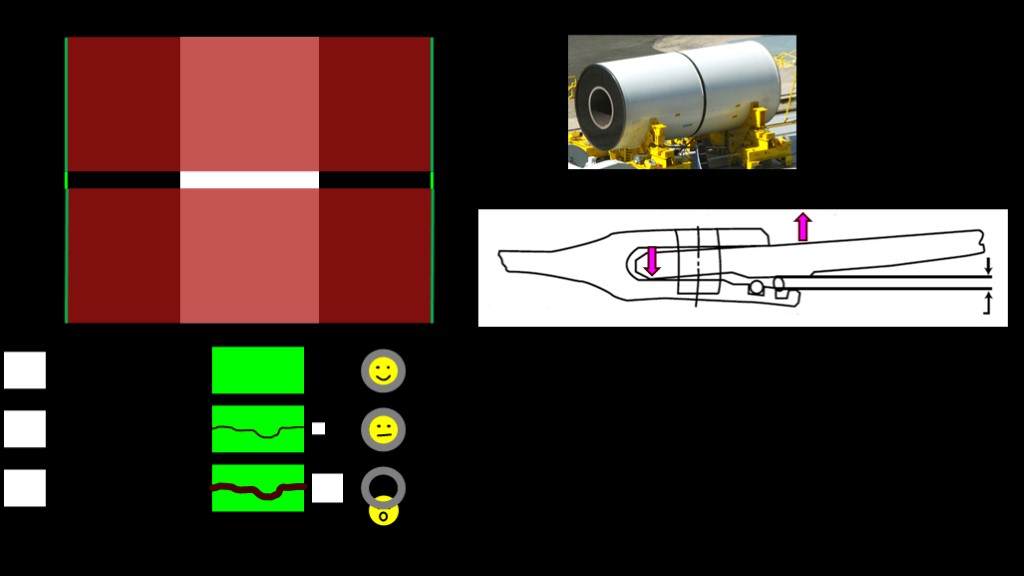
The boosters segments are made of steel a little less than half an inch (13 mm) in thickness. The operating pressure of the motors is about 1000 psi, or 68 bar. The joints have more steel than the middle of the segments, and when pressure is applied that causes the segments to bow out between the joints, as shown in this highly exaggerated drawing. Because steel is a resilient material, they will balloon out initially and then return closer to their original shape.
This ballooning had the potential to affect how the joint performed. Thiokol did an analysis that showed that the operating pressure would cause the o-ring area of the joint to be pressed tightly together, so there was no issue.
One of the requirements for booster acceptance is a hydrostatic burst test. The nozzle end of the rocket is sealed up tightly and the booster is filled with water and pressurized to 150% of the operating pressure to verify that it is strong enough.
For that test, Thiokol engineers placed instruments inside the field joints to track what happened during the test. The test itself was successful, but when they analyzed the data from the field joints, they made a disconcerting discovery.
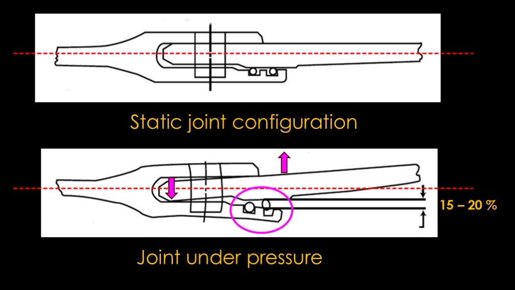
The static joint is fine with everything straight and the orings with proper contact to both the clevis and the tang.
When the joint was under pressure, the walls of both segments bent outwards, as shown in this exaggerated drawing. The tang would bend up and open the gap where the o-rings were located, and the end of the tang would flex the clevis out, also opening the gap where the o-rings were located.
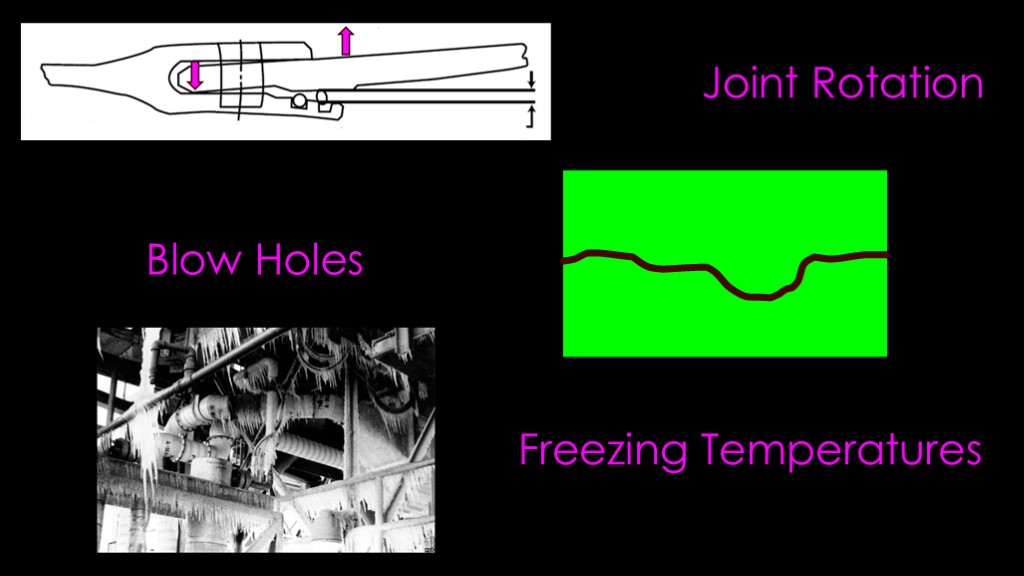
The resulting gap was estimated to be 15 to 20 percent of the diameter of the o rings. They called the phenomena "joint rotation", and it's most pronounced during motor startup when the segment walls balloon the most.

This was a red alert moment...
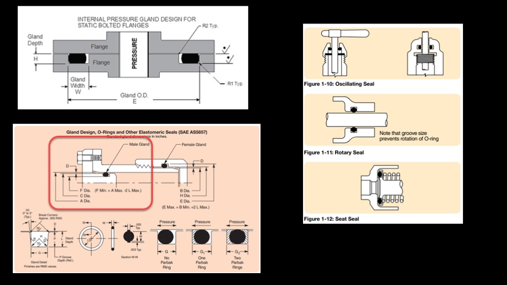
There are numerous o ring design guides out there that give you a ton of information on how to size the grooves, what specific o ring materials to use for a specific application, different types of seal designs, and other information on what makes a good design.
What they don't tell you is what to do when the two surfaces you are trying to seal move apart, because that is not a situation where o rings will work successfully - moving apart reduces the amount of compression in the o ring and therefore the amount of pressure the o ring can seal against. And if the gap is big enough, the o ring won't even touch both surfaces.
Joint rotation means that this is simply not an acceptable design.
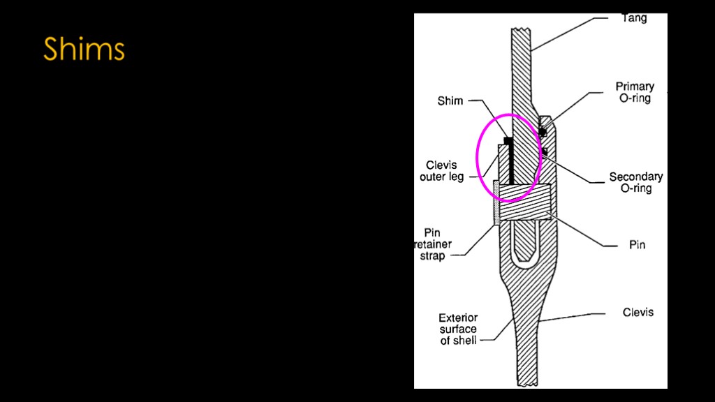
Thiokol did make one change to the joint to reduce the amount of joint rotation; after assembly, a shim was added between the tang and the clevis outer leg to reduce the amount of slop in the joint and therefore reduce the gap at the o rings.
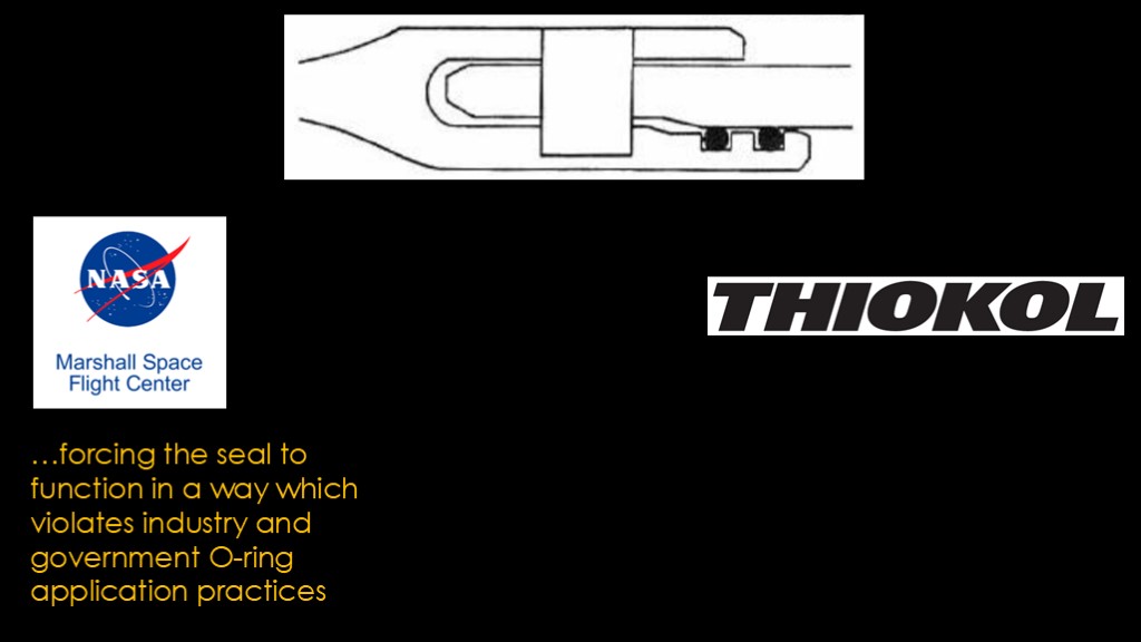
We then get into a contest between Marshall and Thiokol.
The marshall engineers asserted that the current design was "...forcing the seal to function in a way which violates industry and government o ring application practices".
Thiokol asserted that joint rotation was not a significant problem. The real issue for them was that it was 1979, they had already tested 3 motors with acceptable results and they were deep in the manufacture of flight hardware. Modifying the design at this point would not only be expensive, it would lead to a multi-year delay.
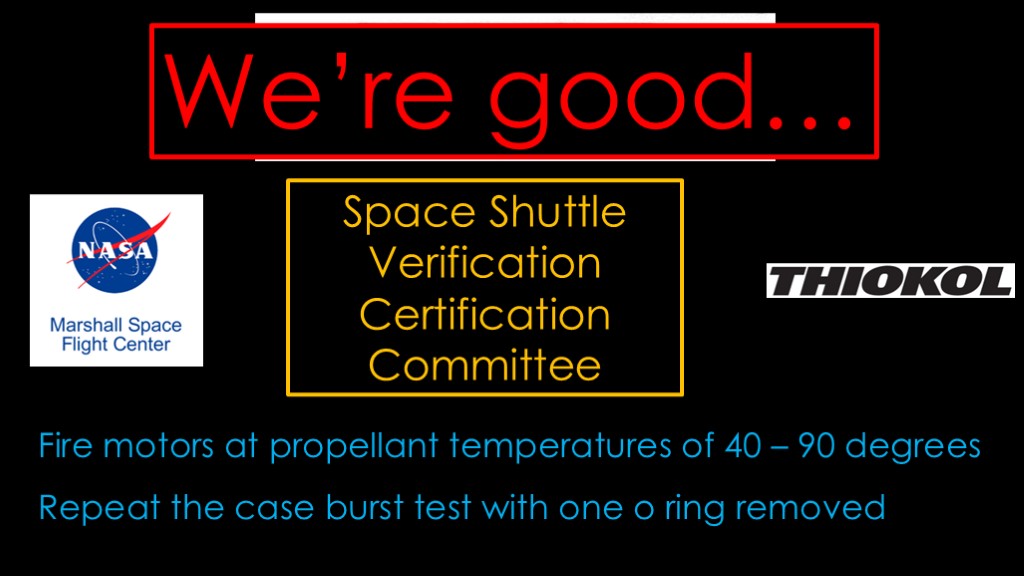
In 1980, NASA empanelled a space shuttle verification and certification committee to look at the flight worthiness of the entire shuttle system.
The concern was primarily about the secondary o ring - the one on the left in this diagram. The committee somehow came to believe that it was there only to test the primary and redundancy was not a requirement.
The committee ended up recommending two things.
The first was to fire test motors at propellant temperatures from 40 to 90 degrees, and the second was to repeat the case burst test with one o ring removed, to verify that the design can function with one o ring.
The NASA shuttle program response can be summarized as "we're good...". No tests were performed and no changes were made.
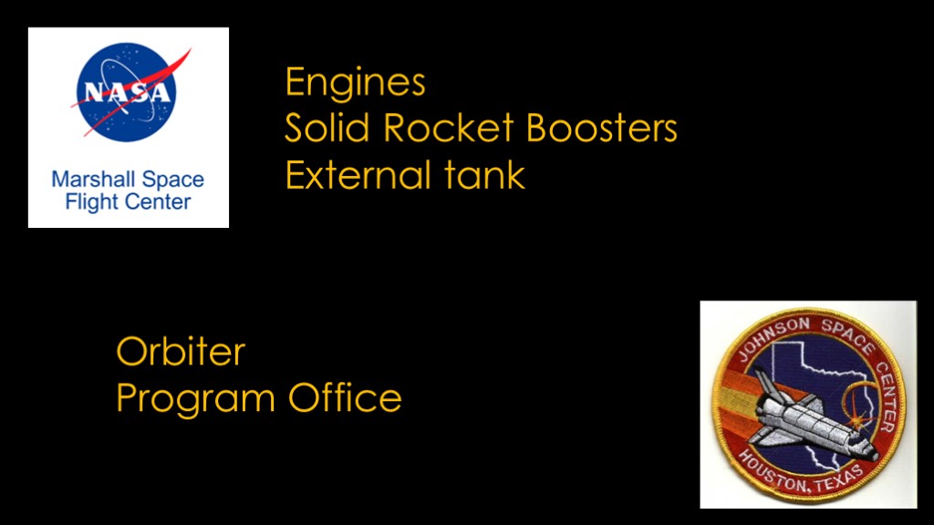
Part of the issue may have been poor communication, but a major part was that Marshall Space Flight Center was responsible for the shuttle engines, solid rocket boosters, and external tank, and the Johnson Space Center in Houston Texas was responsible for the orbiter and the overall program.
It's sometimes better to think of NASA as a loose association of the various centers rather than a conventional organization led by NASA HQ, and that means that the individual centers have their own concerns. Shuttle delays will impact how Johnson is perceived and they want to keep things moving, and that would be true even if the management of the two centers liked each other.
And that's why the flawed design got certified for flight.

The first shuttle flight was on April 12th, 1981, and there were no anomalies with the solid rocket boosters.
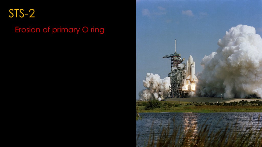
On STS-2, erosion of the primary o ring was found.
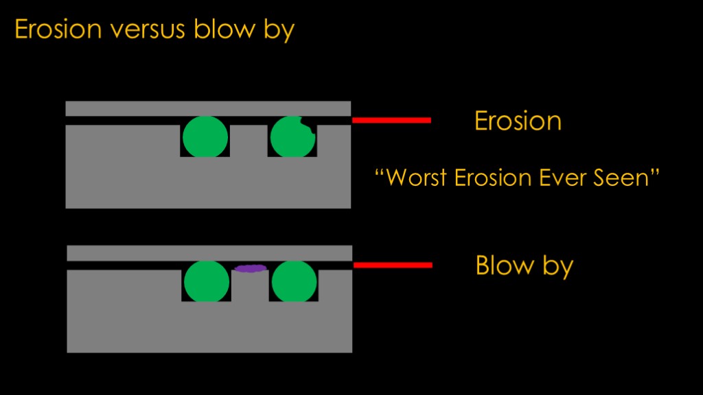
At this point, we need to talk about the two kinds of o ring damage that showed up in the field joints.
The first is erosion. In that case, hot gas comes into the joint and eats away at the o ring. In the STS-2 case, it ate away 20% of the diameter. That's not enough to cause a failure of the seal, but it's something that isn't supposed to happen.
It was worse than any erosion that had been seen in any solid rocket motors with field joints.
The second damage is "blow by", and it occurs when the hot gas gets past an oring. The sign of blow by is soot deposited in the joint after the o ring.
Blow by can happen for multiple reasons. It could be that the erosion is bad enough that the gas can get by, it could be that the oring is too inflexible to deform over to the side, or it could be that the joint opens up and the gap is big enough that the o ring cannot fill it.
Blow by is very bad - it means that your seal on that o ring has failed, and if you get blow by on both o rings, you could end up with an open joint and constant combustion gas leakage.
Though the STS-2 erosion was unexpected, it was not reported to Marshall as a flight anomaly.

There is a widespread belief that NASA's big failure was ignoring a stream of O ring failures. It's useful to look at the information over time
If we look at the o ring issues in the early flights, we find something really weird. STS-2 was the only instance of erosion in the first 9 flights, which means the expected number of issues was 0.11 per flight. It wasn't that NASA had a major string of failures they were ignoring; the reality was that the joints appeared to be working well with only one issue.
During this time period, there were a number of different issues that shuttle was encountering, including cracks in the main engine turbopump blades, issues that appeared to be higher priority.
Then all hell broke lose.
After STS-9, in rapid succession STS-41B, 41C, and 41D flew and they all showed erosion in one of their field joints. The following 2 flights were clean. There were 0.6 expected issues per flight during this period of 5 flights, or 5 times the number of issues in the previous 9 flights.
These woke everybody up; NASA started tracking the issue and Thiokol spun up a team to figure out what was going on.
And to finish the chart, the next 9 flights would only have 3 flights with anomalies, but they were alarming.
STS-51C - the coldest launch so far of the program at 53 degrees - had 3 field joint issues. One of the joints on both boosters showed both erosion and blow by on the primary o ring, and one of those joints showed heat damage on the secondary o ring.
This is the flight that made Thiokol very leery of launching below 53 degrees.
After 6 flights without any field joint issues, STS-61A showed blow by on two o rings in one booster at a launch temperature of 75 degrees.
And then finally STS-61C - the last flight before Challenger on 51L - showed erosion on 1 field joint at 58 degrees. The expected number of issues per flight was 0.66 during this period.
This is really perplexing - bad things are going on all over the place.
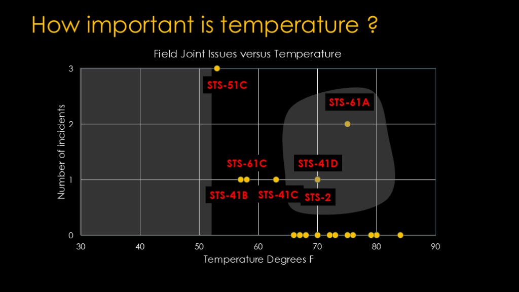
We can plot the flights by temperature and number of issues.
And this is just frankly confusing. STS-51C seems to be a real wakeup call that flying in temperatures below 53 degrees was probably a really bad idea. And every flight colder than 65 degrees had an issue. Temperature matters, and it's well known that O rings get considerably less flexible as the temperature goes down, so there's a good explanation for why low temperatures might be problematic.
But these others indicate that flying in these regions isn't a good idea either.
It would be nice if we had some other data on o ring erosion and booster temperature.

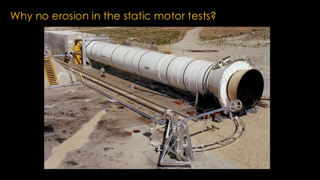
Thiokol did a number of static tests of the solid rocket motors, 7 of them before the first shuttle flight and 4 additional tests in the years before Challenger.
Utah is generally colder than Florida, so they got a nice spread of data at different temperatures. And what did they find.
There were zero field joint issues on any of their tests, including four tests below the 53 degree temperature that had caused so much trouble with STS-51C.
This was perplexing. There was something else going on, something that was different between Thiokol static tests and actual flights.
But before we get to that, we need to expand our knowledge of field joints.
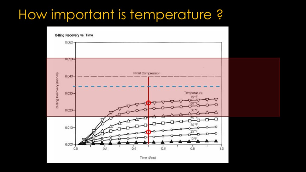
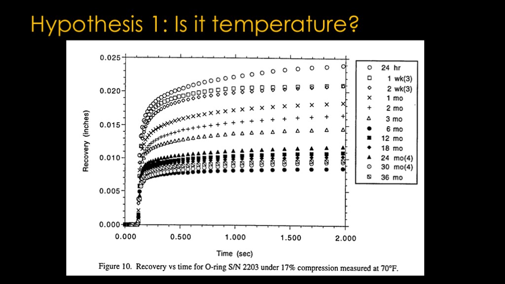
It's well understood that o rings lose flexibility as they get colder. Here is some test data.
Solid rocket motors take about half a second to get to full pressure, so I've included a vertical line at that point.
The chart is a bit confusing. It's showing how much an o ring will expand if you compress it a specific amount
The results here are mostly unsurprising. Even at 75 degrees, the seal only expands to about 65% of its original size. At 30 degrees, it's less than 25%.
But I think this is a bit of a red herring. As I said earlier, o rings are used everywhere and function fine in good designs even in sub zero temperatures.
But this is honestly a weird way to look at things. Let's say your joint opens up 0.02 inches, and your temperature is 75 degrees. At 75 degrees the recovery is about 0.025 inches, so you'll be okay, right?
Wrong. The o ring is in contact with 2 surfaces, but the o ring is barely compressed and it's not going to hold much pressure. It's far better than the case if it's 30 degrees, where you now have a 0.01 inch gap and no pressure seal, but in neither case will the seal perform properly.
Cold o rings look worse, but probably aren't the main driver.
To dig in deeper, we're going to look at the joint anatomy with a lot more detail.
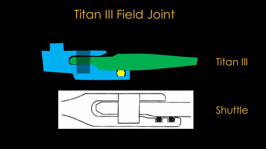
First, we need to look at the Titan III field joint and compare it to the shuttle field joint. They are similar in concept, with the big difference being one o ring in the Titan design and two o rings in the shuttle design.
But how could more o rings be a problem?
We need more information about the rest of the joint.
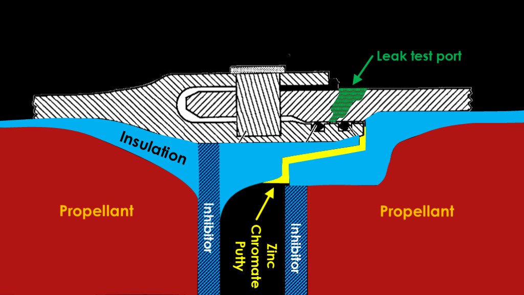
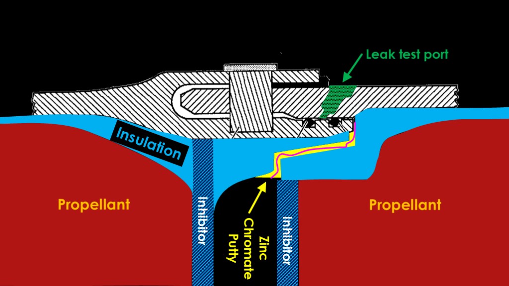
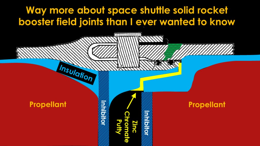
The internal structure of the booster inside the joint is all aimed at protecting the joint.
There is an internal coating of insulation, typically made out of rubber with a reinforcement of chopped Kevlar or carbon fiber along with a flame retardant.
On the inside of that is of course the propellant. At the bottom and top of the segments next to the propellants are what as known as inhibitors, which are propellant-like materials that do not burn quickly. That is to keep the propellant burning from the center out rather than burning in the section between the two segments.
Filling the serpentine channel from the space between the inhibitors and the part of the field joint with the o rings is a flame resistant zinc chromate putty containing asbestos. You've probably guessed that the job of the putty is to keep the combustion gas from getting to the o ring.
The final feature to add is a leak test port. One of the NASA requirements is to ensure that the o rings are properly seated in their grooves, and that is done by pressurizing the space between the o rings with nitrogen through this port. After the test, the port is sealed with a plug. Titan doesn't have a leak test port because it only has a single O ring and this test therefore cannot be performed.
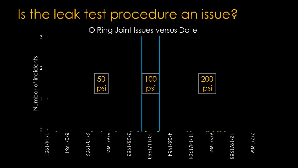
Is the issue something related to the leak test?
For the first 7 flights, NASA applied 50 psi of pressure to verify that the o rings seated, but then a concern was raised that the o ring could be omitted during assembly (really?) or that it might not be seated correctly and that issue could be masked if the putty was solid enough to hold back the pressure.
This is a pretty dubious assertion given that erosion was not an ongoing problem, but NASA and Thiokol elected to increase the pressure to 100 psi. There were no issues for two flights, and then they decided to further increase it to 200 psi, and that is the point where all hell broke loose.
What was happening was known as a "blow hole" - a path from the o ring space through the putty into the engine.
Thiokol knew from their tests that some blow holes occurred during assembly - presumably as trapped air needed to find a way out, with the only exit path through the putty.
When the joint was pressurized for the leak test, it pushed the two O-rings apart, but before the primary o-ring seated against the right side of the groove, some nitrogen leaked past the primary o ring and to the putty, and that pressure needed to go someplace, and that was through the putty.
Going to 200 psi ensured that a bad o ring would be detected by the test, but unfortunately, it apparently made the blowholes through the putty bigger and more significant.
That was a big problem.
When solid rocket boosters are ignited, they start burning in the open core of the propellant and that causes a large pressure spike inside the center of the motor - around 1000 PSI, or about 70 bar.
Between segments, there is a tiny gap between the propellant grains - a gap between the two inhibitors. Before the motor starts, there is no pressure in that gap, but as the motor starts, the high pressure in the core pushes into that gap and slams into the joint at the outside of the segment.
If that pressure wave hits a solid section of putty, it compresses it a bit and maybe the putty gets a little hot, but there is no path for the gas to get to the o ring. The o ring is happy.
If there is a small blow hole path throw the putty, some of that pressure wave makes it through, and it heats up the o ring. If it was just a little pressure against the o ring, that wouldn't be a problem, even if there is some joint rotation that moves the o ring out of position. The o ring might be a little distressed but the joint is functional.
If there is a large blow hole through the putty, we get a lot of gas against the o ring, and if joint rotation or cold temperatures prevent the o ring from sealing, the high pressure in the motor has access to the low pressure past the o rings and we will get flow through the joint. That flow means hot gases increasing the size of the blow hole and eroding the o ring so that it may not be able to seal when the joint closes after the motor is running.
The o ring is very, very sad.
Unfortunately, the change from 50 psi to 200 psi that was intended to improve the integrity of the joint led to blow holes that could channel hot combustion gas directly to the o ring, and the random occurrence or issues was due to the blow holes being different every time the leak test was done.
There's still a puzzle. If blow holes were problematic and cold weather was problematic, why didn't any issues show up in the static tests?
The short answer is that there were no blow holes in the first 10 static test motors. The manager who was in charge of the program at that time decided that the blow holes were flaws and walked inside the motor, inspected all the joints, and repaired any blow holes from the assembly and testing process with new putty and tape. And he didn't tell anybody about it.
That repair process was not done with the vertically assembled motors in Florida, and that meant that there were no static tests with blow holes before shuttle started flying.
That changed with the DM-7 motor, which was the only "flight condition" motor static tested before challenger flew. It was tested at 61 degrees and the blow holes were apparently not bad enough to cause issues.
I should also probably note that the leak test pressures were not available for the static test motors, so it's not clear if they followed the progression from 50 psi to 200 psi.
We now have three probable causes for the failure of the joint during the flight of challenger.
A joint design that is prone to joint rotation and therefore does not provide a proper environment for o-rings to function.
An o ring testing process that created significant blow holes in the Zinc Chromate putty, thereby creating the exact condition that the putty was intended to prevent.
Freezing temperatures that chilled the o rings and made them inelastic.
This is a picture of the launch pad structure taken the morning of the launch.

Now we know enough to discuss the flight...
At SRB startup, the whole shuttle stack vibrates and that causes sideways stress on the boosters and their joints.
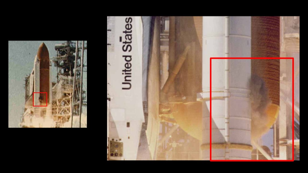
At about half a second, a puff of gray smoke emerged from the aft field joint of the right solid rocket booster and 8 more puffs of smoke escaped at a frequency of about 4 hertz or 4 times a second, approximating the rate at which the structure flexed and the joint opened and closed.
And then something a bit weird happened. The smoke puffs stopped. The joint had closed up. The leading theory is that aluminum oxide from the combustion of the powdered aluminum in the propellant clogged up the joint and stopped the flow.
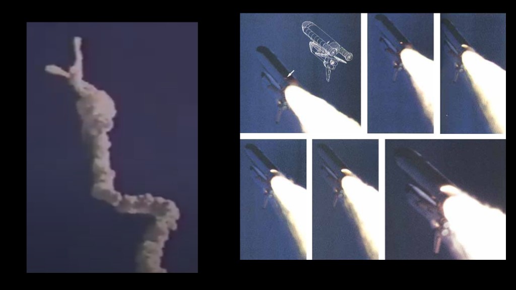
And then at 37 seconds into the flight, the first of several high-altitude wind sheers - layers where wind speed and direction change abruptly - hit the shuttle from the side and recreating the bending conditions that had occurred at launch. That weakened joint failed and soon there was a bright exhaust plume that would ultimately impinge on the external tank and the strut that connected the solid rocket booster to the tank, and that resulted in the explosion.
An image captured by CNN shows the signature of the wind sheer, the crooked exhaust path.
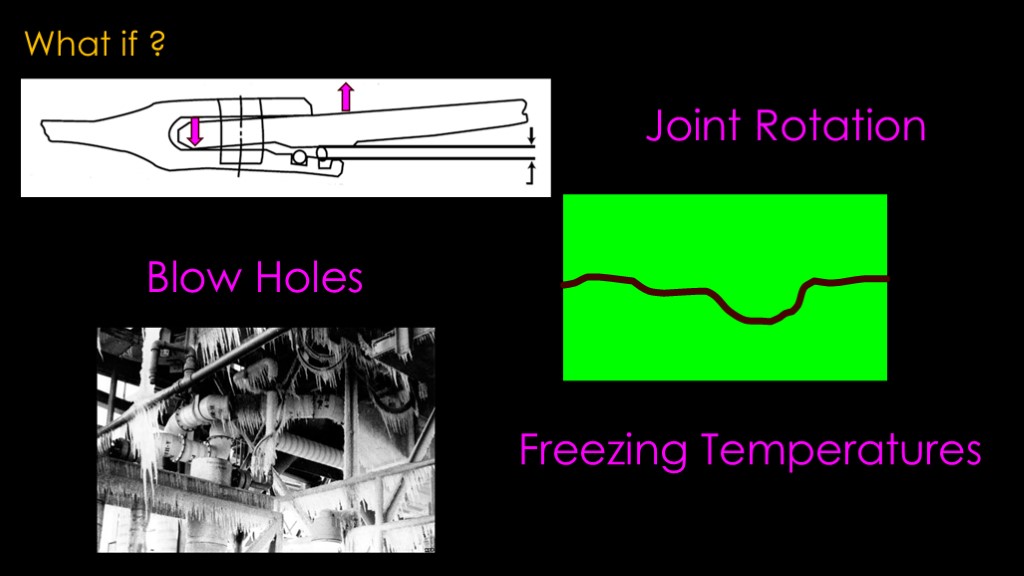
I'm not going to go into the decision making process that led to the decision to launch as it has been talked about endlessly, but I do think it's interesting to consider a few hypotheticals.
First, what if the boosters used either the Lockheed design or the original Thiokol design with the addition of tapered pins? Would Challenger have survived?
I think the Lockheed design was almost immune to joint rotation and the face seal made it very hard to get combustion gas to the o rings, no matter how cold they might be. I do not think that joint would have failed.
Second, what if the blow holes were either minimized by keeping the 50 psi test procedure or by sending somebody inside the SRBs to repair them after it had been stacked and tested? The 50 psi test procedure likely would have helped, but there was sometimes erosion at that pressure - STS-2 was an example - so I think it was maybe okay but that joint was very, very cold. Repaired blow holes was a better bet. Retired Colonel Chuck Yeager commented during the investigation that if they patched the blow holes, he would fly on the shuttle "tomorrow".
Third, what if they waited for higher temperatures to launch? That's a harder one to predict because we don't know how bad the blow holes were. Thiokol said they were okay with launching at 53 degrees because they had the data from 51C and - while there was erosion on both primary and secondary o rings, they did work. The failed joint would have been a lot warmer if it was 53 degrees outside, and that probably would have been enough.
There are two issues that I want to discuss.
The overnight low temperature was 18 degrees, but the solid rocket segments are massive beasts that weigh well over 100 tons, so they don't change temperature very quickly. Thiokol had a model that predicted the joint temperature would be around 27 degrees at launch.
The ice team that looked at the pad overnight recorded an outside temperature of the left SRB of 25 degrees, which was pretty close to the predicted temperature. The right SRB - the one that ultimately failed - was 8 degrees, much colder than the left one.
Another puzzle.
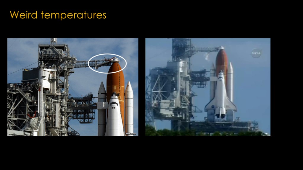
It turns out that the issue is because of the external tank...
The top of the external tank is the oxygen tank and there is a cap - called the beanie cap - that captures the vented oxygen and then releases it back to the atmosphere, as you can see in the video on the right.
After Challenger, Thiokol was trying to figure out if there were any other possible issues that might cause problems for the solid rocket boosters, and the topic of the very low temperatures on the Challenger SRB that failed came up.
Thiokol did some advanced fluid dynamics modeling, and found that if the wind was just right, the very cold gaseous oxygen released from the outlet could be pushed back against the external tank. It was not a problem for the external tank, but under some conditions the gas could curl around and end up cooling off the base of one of the solid rocket boosters. And it turned out, the weather the night before challenger launched appeared to be a match to those conditions.
The failed joint was about 20 degrees colder than expected.
There was also the puzzle of the Titan III. It didn't have a leak test because it only had one o ring and that likely limited any blow holes, but it would still be expected that joint rotation would turn out to be an issue.
NASA and Thiokol had met with the Titan III folks, and they flatly stated that they had never witnessed any erosion of o rings, and did not share any test or flight data with NASA.
During the challenger investigation, a General on the investigation committee obtained data on a planned redesign of the Titan field joint to add a second o ring to the design to deal with seal erosion.
It turned out that the frequency of o ring erosion and charring was 3 times worse on the Titan III SRBs than on shuttle, far different than what the Titan III folks had shared.
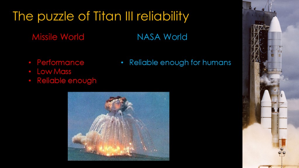
It's likely because of the difference in philosophies between the two worlds.
In the missile world, designers are looking for every advantage - they need high performance and they need to keep mass low to get that performance. They are therefore willing to accept a solution that is reliable enough to get the performance. There are no published reliability rates, but 90% is probably pretty close, and it's not a problem as multiple missiles are allocated to a single target.
NASA needs launchers to be reliable enough for humans, which means a lot more reliable than 90%.
Titan III was seeing significant erosion issues, but it wasn't causing launch failures and therefore the design was good enough for them.
At least for the Titan III. An upgraded version - the Titan 34D - used an extended solid rocket booster with an additional segment, and the additional pressure combined with poor work on the insulation of the motor led to the rupture of the steel casing .
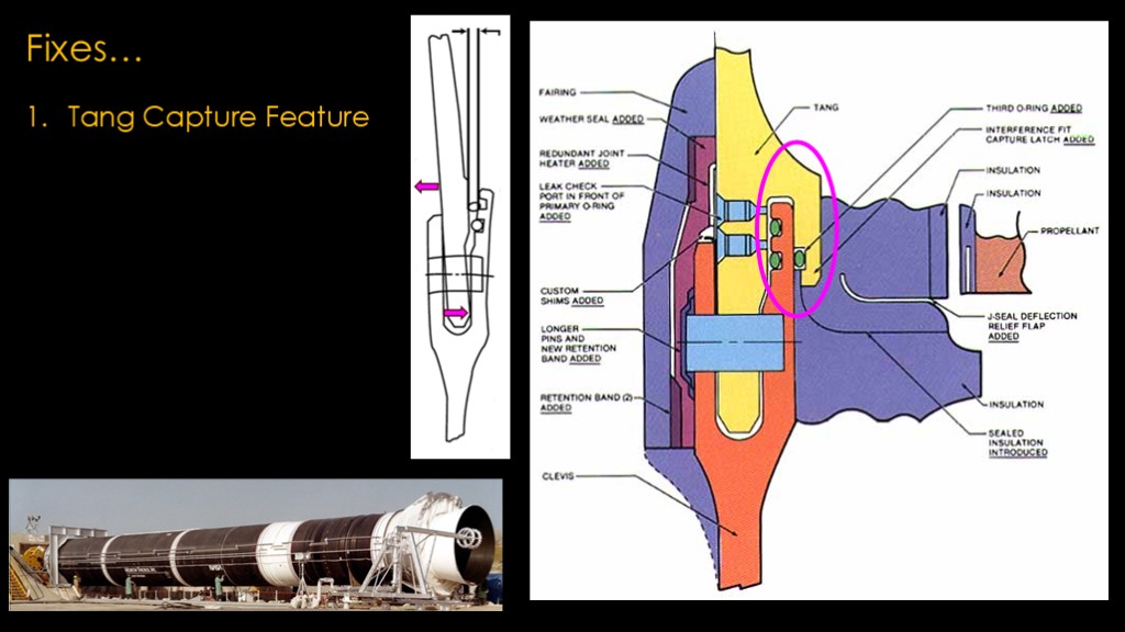
Post challenger, the field joint was redesigned with a bunch of enhancements.
The first was to redesign the tang end of the joint so that it would hook around the inside end of the clevis, preventing the joint rotation that was present in the original design. In addition, a third o ring was added out on the hook.
This was actually not a new design. The plan to launch the shuttle from Vandenberg air force base in California to Polar orbits required a shuttle with spicier performance, and one way to get that was with a solid rocket booster with a lighter case. The FWC - or filament wound case - version of the shuttle SRB was already in early manufacturing in the summer of 1985, and since Thiokol's models predicted that joint rotation would be worse with the more flexible cases, they came up with this design.
They also tried to get NASA to switch over to this design for the normal shuttle SRBs, but NASA was not interested.
That covers the joint rotation problem.
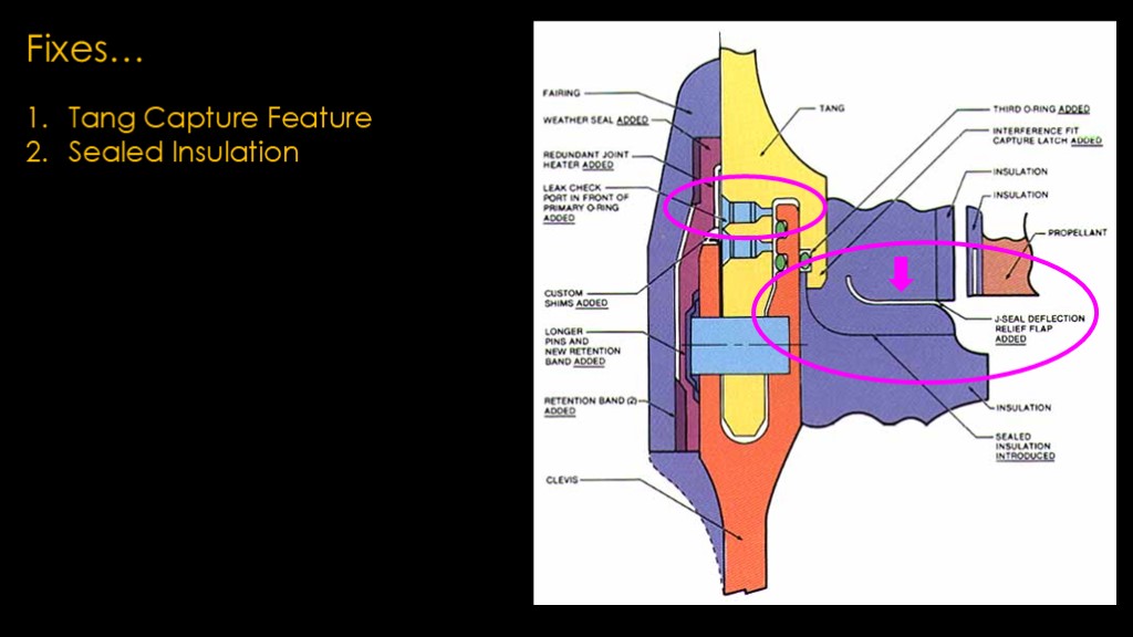
To deal with the blow holes, they changed the design so that the insulation in the two segments was bonded together, and added this cute little "J shaped" relief flap so that it if the joint flexed, the relief flap would flex rather than opening up the bonded insulation seal.
That's clearly a better design for the inside of the joint, but it increases the problem of testing the o ring as there is really no place for pressurization test gas to go if it gets by the upper o ring. The design therefore adds a second leak check port in front of the primary ring. You can pressurize the primary o ring to your heart's content and any gas that gets by the o ring will merely come out the new leak check port.
This is a small change that probably should have been part of the original design.
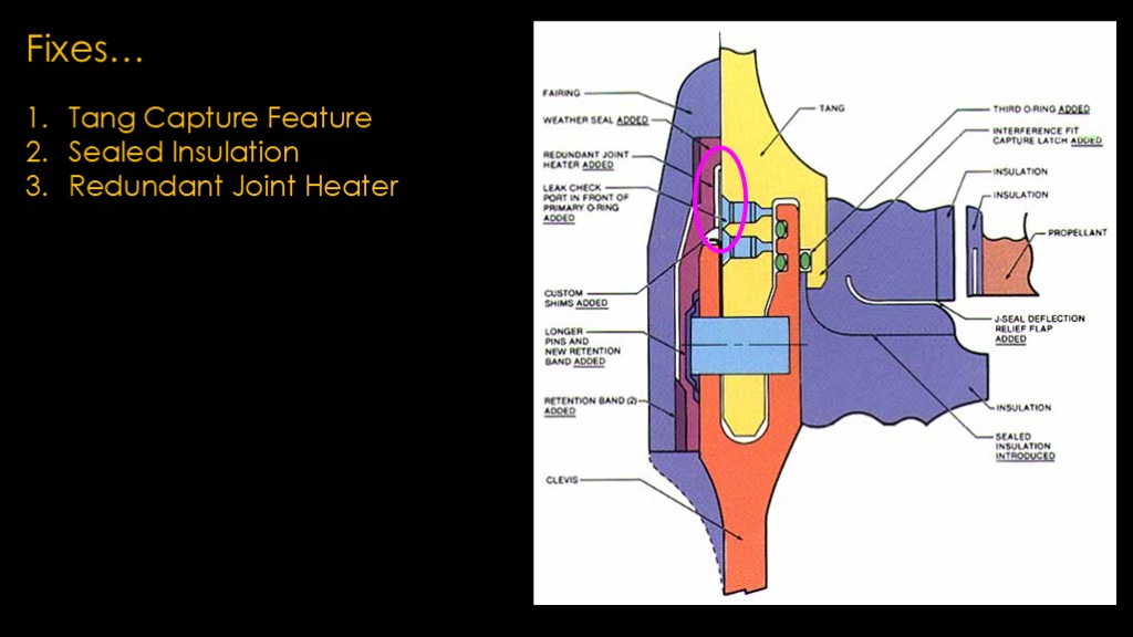
The third issue was cold o rings, and the new design added redundant joint heaters, which could keep the o rings nice and warm, or at least quite a bit warmer. Joint heaters would also have been a good addition to the original design, but it wasn't clear that cold temperature was the big driver for erosion.
That covers all three of the main issues.
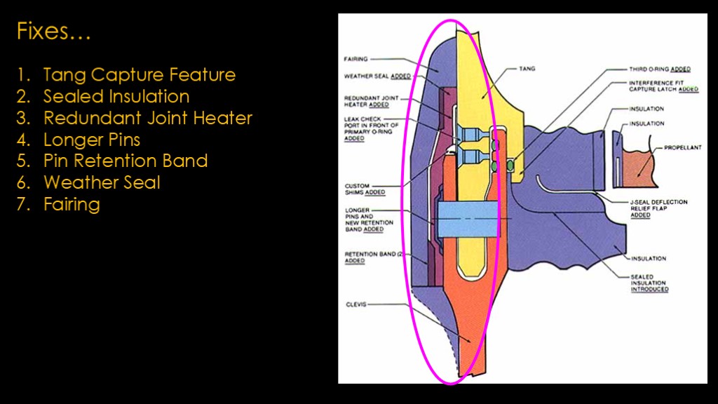
In addition, they made the pins longer, added a band around the booster to hold the pins in, added a weather seal to keep water out of the joint - frozen water in the joint might have been contributory in Challenger - and finally, covered the whole thing with a fairing.
This design was tested extensively with introduced flaws in different areas and it performed very well, and it flew for the rest of the shuttle program without issue and is still used in the SLS solid rocket boosters.
And that's the story of the field joint.
I hope you enjoyed this edition of "way more about space shuttle solid rocket booster field joints than I ever wanted to know"

I used two great resources in developing the video.
The first is the report by the commission that investigated the challenger accident. This is known as the "Rogers commission" after the chair of the commission, William Rogers, and the report is known as the Roger's report.
The second is the wonderful book "Truth, Lies, and O-Rings" by Allan McDonald, the head of Solid Rocket Boosters at Thiokol corporation. The book covers his time before Challenger, the time around Challenger, and his role in the booster redesign after Challenger. And no, he was not the manager fixing the blow holes inside the booster.
It's a great book, but I'll warn you that you will be really pissed off multiple times when you read it.
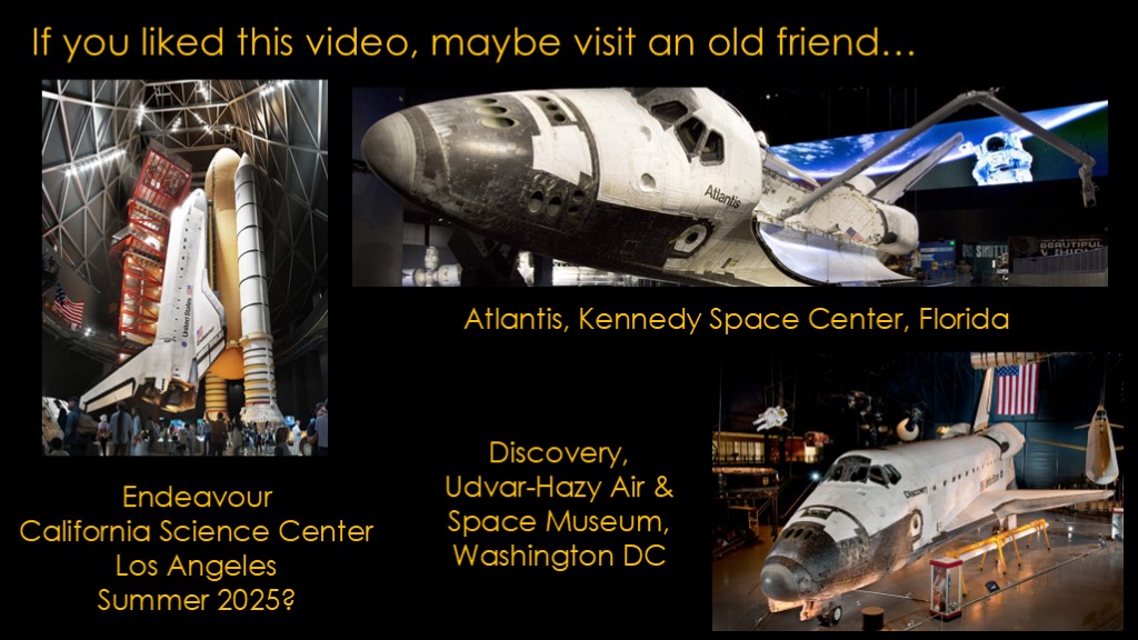
If you liked this video, maybe you would like to visit an old friend...
Atlantis is on display at Kennedy Space in Florida, Discovery is on display at the Udvar-Hazy wing of the Air and Space Museum at Dulles Airport in Washington DC.
But by far the most impressive display will be the Endeavour display currently being constructed at the California Science Center in Los Angeles. It will feature Endeavour in flight configuration with the last flight qualified external tank and mated to real solid rocket boosters. The exhibit is currently scheduled to open in the summer of 2025, and I expect it to be glorious.
It's actually a little worse than that.
After challenger, the air force was worried about the solid rocket boosters used on titan and they commissioned a study that looked at the resilience of the o ring material - the same material used on the shuttle SRBs - over time.
The previous chart used a compression time of 2 hours, and this study looked at compression times from 1 day all the way up to 3 years. A 1 month compression time reduces the recovery about 25%, so with typical shuttle assembly and launch delays, the ability to deal with gaps is less.
This is why NASA has limits on how long the solid rocket boosters on SLS can sit around before being flown, though the current joint design is far better.
https://apps.dtic.mil/sti/pdfs/ADA402958.pdf
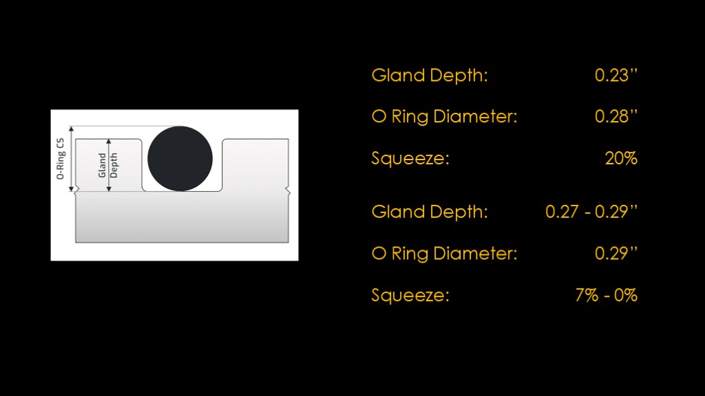
O rings are generally designed to have 20-30% compression to provide enough seal to prevent leaks.
If we look at the shuttle design, the gland depth for the o ring was about 0.23 inches, and the o ring diameter was about 0.28 inches, providing a squeeze of 20%, an adequate amount.
But that assumes that the face that the o-ring is sealing against doesn't move at all. If the joint is opened by 0.04 to 0.06", that bumps up the gland depth to 0.27 - 0.29", and the squeeze is reduced from 7% to 0%. Neither of those are going to provide a proper seal.
Did I mention how bad this design is?

Let's put ourselves in NASA's shoes. They have flown STS-2 and seem some significant erosion, they've flown a bunch of other missions with varying results. What can we figure out from the data?

What can we conclude about temperature?
There's good reason to expect that lower temperatures are worse for the joint performance and the analysis of Challenger data supports that.
But we have a weird conundrum. We're still seeing some issues at high temps and the Titan design has flown for years with only a single o ring with high reliability.
Is there something else going on?
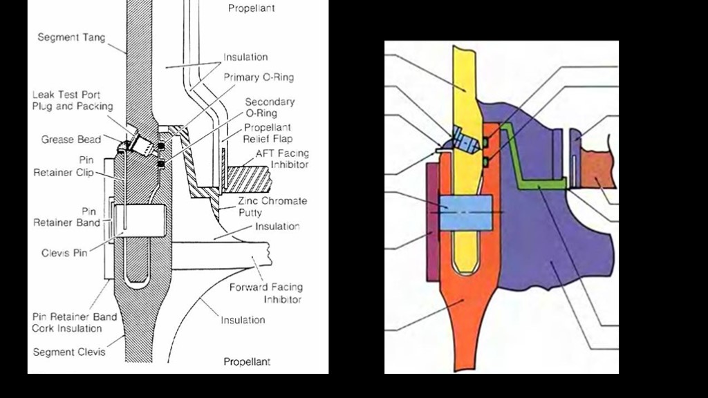
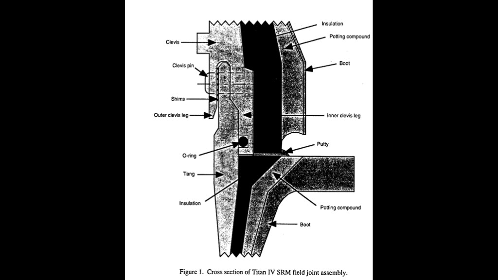
In the earlier drawings, I kept things simple but the cross section of the joint is actually quite a bit more complicated
There are specific features in the joint to keep the hot combustion gases away from it. There is insulation between the segment casing and the propellant, and there are two structures called "inhibitors" that are designed to guide the gases towards the center of the motor and away from the field joint. And there is a crooked path where the insulation of the two segments join, and that joint is filled with a zinc chromate putty. All of this was carefully designed to keep the gases away. This approach would often be called "defense in depth" - not relying on a single feature to keep things safe.
There's another little feature that is often overlooked - the leak test port. NASA had a requirement that there be a way to test the joint to ensure that the o-ring was properly installed, and this was done by hooking pressurized air source to the leak test port and pressurizing the joint. That pressure would force the two o-rings apart and if the pressure held, that meant that the o-rings were properly installed in the grooves and functional.
The other additional complexity is a leak test port. That allowed the space between the two o-rings to be pressurized and to verify that both o-rings were properly seated, a verification requirement.
This was a significant change from the design used in the Titan solid rocket motors.
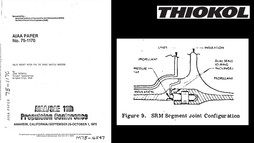
Thiokol was awarded the solid rocket booster contract in November of 1973.
In 1975 they presented a paper on their design at a conference, and it contains the same joint design, with straight pins and one o ring in the bore and one on the face.